
New Holland LM5040, LM5060, LM5080 Telehandler Service Manual
$59.99
Covers: New Holland LM5040, LM5060, LM5080 Telehandler
Pages: 733
Format: PDF file (zipped)
File size: 266mb
Compatibility: Windows/Mac computers
Notes: Instant digital download only – no printed copy or CD-ROM media.
This downloadable service manual covers service procedures for the New Holland LM5040, LM5060 and LM5080 telehandler. In this service manual you will find detailed step-by-step instructions, illustrations, specifications and diagrams. View the PDF service manual on your computer or print off detailed service and maintenance instructions as needed.
Latest edition. CNH F4 engine repair manual sold separately.
Topics:
GENERAL INFORMATION
- General instructions
- Safety rules
- Product identification
- Environmental considerations
- Maintenance techniques
ENGINE
- Main engine specifications
- General engine specifications
- General information on F4GE9484J engine
- Removal and installation of engine and radiator
- Troubleshooting
- Tightening torques
- Special tools
TRANSMISSION
- Powershift transmission
- Transmission assembly
- Drop box assembly
- Operation of gearbox
- Transmission and hydraulic oil circuit diagrams
- Operation of modulating valve
- Torque converter and oil cooler hydraulic circuit
- Troubleshooting guide
- Troubleshooting procedures
- Troubleshooting
- Pressure tests on clutch and high pressure circuit
- Pressure tests on torque converter and oil cooler hydraulic circuit
- Test points
- Assembly instructions
- Transmission overhaul
- APC122 electronic control with Powershift transmission (optional)
- Power Shuttle transmission (optional)
- Power shuttle transmission assembly
- Assembly instruction
- Operation of gearbox
- Activated solenoids power flows and hydraulic circuit
- Transmission overhaul
- Brake pad substitution and adjustment of parking brake caliper (Powershift and Powershuttle Transmission)
- Special tools
FRONT AXLE
- Technical data
- Description
- Operation
- Troubleshooting
- Wheel toe–in check
- Component overhaul
- Front axle removal procedure
- Front axle overhaul
- Removing the steering cylinders
- Disassembly of 45% limited slip differential
- Installation and adjustment of axle drive pinion
- Front drive shaft
REAR AXLE
- Technical data
- Description
- Operation diagram
- Rear drive shaft
- Component overhaul
- Rear axle removal procedure
- Overhaul
- Special tools
BRAKING SYSTEM
- Service brakes
- Trailer brake
- Parking brake
- Brake disc adjustment
- Troubleshooting
- Brakes disassembly
HYDRAULIC SYSTEM
- Technical data
- Steering system hydraulic circuit
- Introduction
- Steering valve
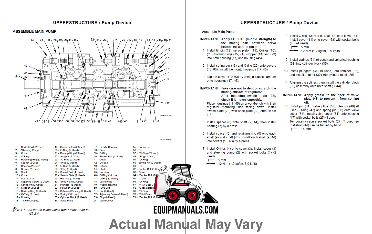
- Telescopic boom hydraulic circuit
- Component operation
- Hydraulic pump
- Pressure reducing valve
- Front loader controls/ operation
- Balancing valves
- Power steering (OSPQ)
- Telescopic boom control valve
- Auxiliary functions control valve
- Cylinders
- Chains
- Boom sections
- Ride Control system (optional)
- Floating boom control switch (optional)
- Continuous flow control switch (optional)
- Reversible fan (optional)
ELECTRICAL SYSTEM
- Electrical system – general
- Electrical equipment specifications
- Electrical system and fuses
- Controls and instruments
- SAR – Anti-Tipping System
- Bulb replacement
- Protecting the electrical systems during charging or welding
- Starting the machine using jump leads
- Temporary wiring repairs
- Electrical system – general fault finding
- Circuit diagrams
- List of connectors
- List of components
- How to use the circuit diagrams
- Diagram 1: Starting/recharge/warning lights/indicators
- Diagram 2: Transmission
- Diagram 3: Wheel alignment/solenoid valves/brake system
- Diagram 4: Boom control
- Diagram 5: Chassis leveling (LM5080 only)
- Diagram 6: Lights/windscreen wiper
- Diagram 7: Work lights/beacon
- Diagram 8: Anti–tipping system / site-street switch / roof wiper
- Diagram 9: Heater, radio/trailer socket/interior light
- Diagram 10: Air conditioning system
- Diagram 11: Rear attachment (optional)
- Diagram 12: Reversible fan (optional)
- Diagram 13: Ride Control system (optional)
- Diagram 14: Floating boom (optional)
AIR CONDITIONING SYSTEM
- Air conditioning system
- Operation
- Cab heating–ventilation controls
- Components
- Precautions for use
- Connections for servicing tools (recovery and recharge station)
- Draining the refrigerant
- Recharging with refrigerant
- Leak test
- Special tools
- Troubleshooting
How does this work?
It’s simple – after purchasing this manual through our secure checkout, a download link will be sent to the email address you specify at checkout. You have up to 90 days to retrieve and save the file. Once saved, the manual is yours for good.
Have any questions or need more details? Contact Us

Reviews
There are no reviews yet.