Caterpillar C10, C12 (1YN, 2PN) Diesel Engine Service Manual Set
$44.99
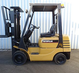
Covers: Cat C10, C12 diesel engine with 1YN or 2PN serial number prefix
Pages: 266
Format: PDF file
File size: 8mb
Compatibility: Windows/Mac computers
Notes: Instant digital download only – no printed copy or CD-ROM media.
This downloadable 4-volume PDF service manual set contains specifications, service and rebuild procedures, operating, and testing/adjusting information for the Caterpillar C10, C12 (1YN, 2PN diesel engines. Over 200 pages of the detailed OEM information for the engine are included in this download. The service manual set follows the manufacturer’s standards for service and repair, and is a must for all diesel mechanics. All pages are searchable and printable. View pages on your computer or print them off for the shop without worrying about dirtying an expensive book, saving your business time and money.
This download includes:
- 1YN1-Up, 2PN1-Up Specifications
- 1YN1-Up, 2PN1-Up Systems Operation, Testing and Adjusting
- 1YN1-Up, 2PN1-Up Disassembly and Assembly
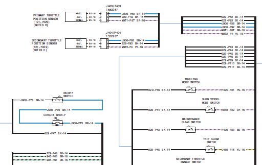
- 1YN 2PN Wiring Schematic
Specifications Section
Engine Design
Fuel Transfer Pump
Fuel Lines
Fuel Filter (Primary)
Fuel Filter and Water Separator
Electronic Unit Injector
Electronic Unit Injector Mechanism
Electronic Unit Injector Rocker Arm
Electronic Unit Injector Wiring
Lifter Group
Rocker Shaft
Valve Mechanism
Valve Mechanism
Valve Rocker Arm
Valve Mechanism Cover
Cylinder Head Valves
Cylinder Head
Compression Brake
Compression Brake
Turbocharger
Exhaust Manifold
Camshaft
Engine Oil Filter Base (166-1329 Oil Filter Base)
Engine Oil Pump
Engine Oil Pressure
Engine Oil Pan
Coolant Conditioner Base
Water Temperature Regulator
Cylinder Block
Cylinder Liner
Cylinder Liner Projection
Crankshaft
Crankshaft Seals
Vibration Damper and Pulley
Connecting Rod Bearing Journal
Main Bearing Journal
Connecting Rod
Piston and Rings
Piston Cooling Jet
Housing (Front)
Gear Group (Front)
Rear Power Take-Off (RPTO)
Flywheel
Flywheel Housing
Engine to Transmission Adapter
Belt Tension Chart
Belt Tensioner
Auxiliary Drive Pulley
Fan Drive
Alternator and Regulator
Electric Starting Motor
Electrical Ground Stud
Coolant Temperature Sensor
Fuel Temperature Sensor
Engine Oil Pressure Sensor
Boost Pressure Sensor
Atmospheric Pressure Sensor
Inlet Air Temperature Sensor
Speed and Timing Sensor
Accelerator Pedal Position Sensor
Systems Operation Section
Engine Design
General Information
Glossary of Electronic Control Terms
Electronic Control System Components
Fuel System
Air Inlet and Exhaust System
Lubrication System
Cooling System
Basic Engine
Rear Power Take-Off (RPTO)
Compression Brake
Electrical System
Testing and Adjusting Section
Fuel System
Electronic Control System
Air Inlet And Exhaust System
Lubrication System
Cooling System
Basic Block
Compression Brake
Electrical System
Belt Tension Chart
Disassembly and Assembly Section
Summary of Revisions
Fuel Priming Pump – Remove and Install
Fuel Filter Base – Remove and Install
Fuel Transfer Pump – Remove
Fuel Transfer Pump – Install
Fuel Manifold – Remove
Fuel Manifold – Install
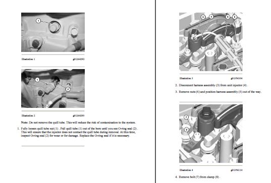
Electronic Unit Injector – Remove
Electronic Unit Injector – Install
Electronic Unit Injector Sleeve – Remove
Electronic Unit Injector Sleeve – Install
Turbocharger – Remove
Turbocharger – Install
Exhaust Manifold – Remove and Install
Inlet Manifold – Remove
Inlet Manifold – Install
Inlet and Exhaust Valve Springs – Remove and Install
Inlet and Exhaust Valves – Remove and Install
Inlet and Exhaust Valve Guides – Remove and Install
Inlet and Exhaust Valve Seat Inserts – Remove and Install
Engine Centrifugal Oil Filter – Remove and Install
Engine Oil Filter Base – Remove
Engine Oil Filter Base – Disassemble
Engine Oil Filter Base – Assemble
Engine Oil Filter Base – Install
Engine Oil Cooler – Remove
Engine Oil Cooler – Install
Engine Oil Pump – Remove
Engine Oil Pump – Disassemble
Engine Oil Pump – Assemble
Engine Oil Pump – Install
Water Pump – Remove
Water Pump – Disassemble
Water Pump – Assemble
Water Pump – Install
Water Temperature Regulator – Remove and Install
Water Outlet Manifold – Remove
Water Outlet Manifold – Install
Flywheel – Remove
Flywheel – Install
Crankshaft Rear Seal – Remove
Crankshaft Rear Seal – Install
Crankshaft Rear Seal Carrier – Remove and Install
Flywheel Housing – Remove and Install
Rear Power Take-Off (RPTO) – Remove
Rear Power Take-Off (RPTO) – Install
Vibration Damper and Pulley – Remove and Install
Crankshaft Front Seal – Remove
Crankshaft Front Seal – Install
Front Cover – Remove
Front Cover – Install
Gear Group (Front) – Remove
Gear Group (Front) – Install
Housing (Front) – Remove
Housing (Front) – Install
Accessory Drive – Remove
Accessory Drive – Disassemble
Accessory Drive – Assemble
Accessory Drive – Install
Valve Mechanism Cover – Remove and Install
Valve Mechanism Cover Base – Remove and Install
Compression Brake – Remove
Compression Brake – Disassemble
Compression Brake – Assemble
Compression Brake – Install
Rocker Shaft and Pushrod – Remove
Rocker Shaft – Disassemble
Rocker Shaft – Assemble
Rocker Shaft and Pushrod – Install
Cylinder Head – Remove
Cylinder Head – Install
Lifter Group – Remove and Install
Camshaft – Remove
Camshaft – Install
Camshaft Gear – Remove and Install
Camshaft Bearings – Remove
Camshaft Bearings – Install
Engine Oil Pan – Remove and Install
Cylinder Liner – Remove
Cylinder Liner – Install
Piston Cooling Jets – Remove and Install
Pistons and Connecting Rods – Remove
Pistons and Connecting Rods – Disassemble
Pistons and Connecting Rods – Assemble
Pistons and Connecting Rods – Install
Connecting Rod Bearings – Remove
Connecting Rod Bearings – Install
Crankshaft Main Bearings – Remove
Crankshaft Main Bearings – Install
Crankshaft – Remove
Crankshaft – Install
Crankshaft Gear – Remove and Install
Bearing Clearance – Check
Coolant Temperature Sensor – Remove and Install
Engine Oil Pressure Sensor – Remove and Install
Speed/Timing Sensor – Remove and Install
Belt Tensioner – Remove and Install
Engine Control Module – Remove and Install
Alternator – Remove and Install
Electric Starting Motor – Remove and Install
Air Conditioner Support Bracket – Remove and Install
Air Compressor – Remove and Install
Air Compressor Drive Gear – Remove
Air Compressor Drive Gear – Install
Foldout Size Wiring Schematics
Engine Harness Wiring Diagram
OEM Vehicle Harness Wiring Diagram
Basic Electrical Troubleshooting and Diagnostic Code List
Index
How does this work?
It’s simple – after purchasing this manual through our secure checkout, a download link will be sent to the email address you specify at checkout. You have up to 90 days to retrieve and save the file. Once saved, the manual is yours for good.
Have any questions or need more details? Contact Us